
No products in the cart.
16%

HX711 ADC Converter Breakout Module for Load Cell Weight
In Stock
In Stock
Add to WishlistRemove from Wishlist
Add to Wishlist
Description
Description
The Load Cell Amplifier and ADC Module is a small breakout board for the HX711 IC that allows you to easily read load cells to measure weight. By connecting the module to your microcontroller you will be able to read the changes in the resistance of the load cell and with some calibration you’ll be able to get very accurate weight measurements. This can be handy for creating your own industrial scale, process control, or simple presence detection.
The HX711 uses a two wire interface (Clock and Data) for communication. Any microcontroller’s GPIO pins should work and numerous libraries have been written making it easy to read data from the HX711. Check the hookup guide below for more information.
Load cells use a four wire wheatstone bridge to connect to the HX711. These are commonly colored RED, BLK, WHT, GRN, and YLW. Each color corresponds to the conventional color coding of load cells:
- Red (Excitation+ or VCC)
- Black (Excitation- or GND)
- White (Amplifier+, Signal+, or Output+)
- Green (A-, S-, or O-)
- Yellow (Shield)
The YLW pin acts as an optional input that is not hooked up to the strain gauge but is utilized to ground and shield against outside EMI (electromagnetic interference). Please keep in mind that some load cells might have variations in color coding.
Features:
- Two selectable differential input channels
- On-chip active low noise PGA with selectable gain of 32, 64 and 128
- On-chip power supply regulator for load-cell and ADC analog power supply
- On-chip oscillator requiring no external component with optional external crystal
- On-chip power-on-reset
- Simple digital control and serial interface: pin-driven controls, no programming needed
- Measurement Resolution: 24 bit
- Selectable 10SPS or 80SPS output data rate
- Simultaneous 50 and 60Hz supply rejection
- Current consumption including on-chip analog power supply regulator:
- normal operation < 1.5mA,
- power down < 1uA
- Operation supply voltage range: 2.7V ~ 5.5V
- Operation temperature range: -40 ~ +85℃
Pinouts
Analog Side
- E+ : Excitation positive
- E- : Excitation negative
- A- : Channel A Negative Input
- A+ : Channel A positive Input
- B- : Channel B Negative Input
- B+ : Channel B positive Input
Digital Side
- GND: 0V / Ground Power Connection
- DT: Data IO Connection
- SCK: Serial Clock Input
- VCC: Power Input
Documents and Downloads
- HX711 Datasheet
- HX711 and Load Sensor Hookup Guide
- HX711 Arduio Library
- HX711 Example Source Codes for Arduino
Only logged in customers who have purchased this product may leave a review.
Related products
14%

Current Sensor ACS712 (AC or DC) 5A
Original price was: EGP150.00.EGP130.00Current price is: EGP130.00. Add to cart


15%
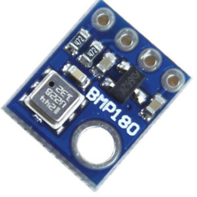
Barometric Pressure Sensor and Temperature Compensation (BMP180)
Original price was: EGP175.00.EGP150.00Current price is: EGP150.00. Add to cart
35%

DHT22 Module (Precision Digital Temperature & Humidity Sensor)
Original price was: EGP350.00.EGP230.00Current price is: EGP230.00. Add to cart

- Image
- SKU
- Rating
- Price
- Stock
- Availability
- Add to cart
- Description
- Content
- Weight
- Dimensions
- Additional information
Reviews
There are no reviews yet.