74266 (Quad 2-input Multiplexer with Buffered Outputs )
Description
The 74266 is a quad 2-input multiplexer with buffered outputs. This IC is used in digital circuits where multiple input signals need to be selected and passed through to the outputs based on control signals.
74266 IC Description:
The 74266 is a quad 2-input multiplexer IC, which means it contains four independent multiplexers, each of which can select one of two inputs to pass through to its output. The selection of which input is passed to the output is controlled by a select input (usually denoted as S or Sel), and the outputs are buffered, meaning the IC can drive higher current to the load, making it suitable for driving loads like LEDs or other devices.
Key Features:
- Quad 2-Input Multiplexer: The IC contains four 2-input multiplexers, allowing it to select one of two inputs to pass through to the output.
- Buffered Outputs: The IC has buffered outputs, meaning it can drive a higher load or provide better signal integrity over longer distances.
- Control via Select Input: Each multiplexer has a control input (often labeled S or Sel) that determines which input is passed to the output.
- CMOS Technology: Like most of the 7400 series, the IC is based on CMOS technology, providing low power consumption and high noise immunity.
- Wide Voltage Range: The IC typically operates within the voltage range of 4.5V to 5.5V, compatible with most standard logic circuits.
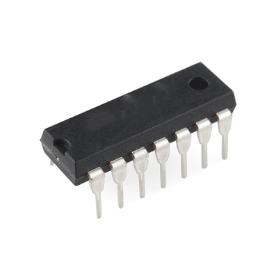
Pin Configuration (14-pin package):
Here’s the standard pinout for the 74266 IC:
- Pin 1: Output of the first multiplexer (Y1).
- Pin 2: Input 1 of the first multiplexer (A1).
- Pin 3: Input 2 of the first multiplexer (B1).
- Pin 4: Select (S) input for the first multiplexer.
- Pin 5: Output of the second multiplexer (Y2).
- Pin 6: Input 1 of the second multiplexer (A2).
- Pin 7: Input 2 of the second multiplexer (B2).
- Pin 8: Ground (GND).
- Pin 9: Output of the third multiplexer (Y3).
- Pin 10: Input 1 of the third multiplexer (A3).
- Pin 11: Input 2 of the third multiplexer (B3).
- Pin 12: Select (S) input for the third multiplexer.
- Pin 13: Output of the fourth multiplexer (Y4).
- Pin 14: Input 1 of the fourth multiplexer (A4).
How it Works:
Each of the four multiplexers in the 74266 IC has two inputs (A and B), one output (Y), and a control select (S) input. Based on the value of the select input, the IC will pass either input A or input B to the output Y:
- If S = 0, the output Y will be equal to A.
- If S = 1, the output Y will be equal to B.
The select signal controls which input is passed to the output, allowing one of two possible data paths to be chosen.
Applications:
- Signal Routing: The 74266 can be used to route digital signals to different parts of a circuit based on a control input. This makes it useful in applications like multiplexing, where you need to select between two signals.
- Data Selection: In systems where you have two data sources and need to select one of them based on a control signal (e.g., selecting between two microcontroller outputs or sensor inputs), the 74266 is ideal.
- Switching Circuits: The IC can function as a digital switch in circuits that require the switching of one of two digital signals to a common output, such as in multiplexed data lines.
- Memory and Register Selectors: In systems that use multiple memory banks or registers, the 74266 can be used to select which memory location or register is accessed.
Electrical Characteristics:
- Supply Voltage (Vcc): Typically 5V (with a range of 4.5V to 5.5V).
- Current Consumption: Being based on CMOS technology, the IC has low power consumption during operation.
- Output Drive Capability: The buffered outputs allow for higher drive strength, making the IC suitable for use with various types of loads, including LEDs and other low-power devices.
Example Use Case:
If you need to select between two signals (say, two digital sensors or switches), you can use the 74266 to route one of the two signals to a common output. By applying a control signal (select input S) to choose between the two inputs (A or B), the selected signal will be passed to the output Y. This could be part of a more complex system like a data bus selector or signal multiplexer in communication circuits.
Let me know if you need more detailed information or a specific example circuit!
Only logged in customers who have purchased this product may leave a review.
- Image
- SKU
- Rating
- Price
- Stock
- Availability
- Add to cart
- Description
- Content
- Weight
- Dimensions
- Additional information


Reviews
There are no reviews yet.