74151 (8-to-1 multiplexer)
Description
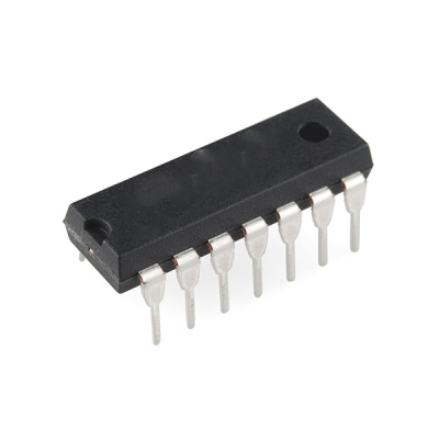
The IC 74151 is a 8-to-1 multiplexer (MUX) from the 7400 series of TTL (Transistor-Transistor Logic) ICs. A multiplexer is a device that selects one of many input signals and passes it to the output based on a set of control signals. The 74151 is a high-speed multiplexer that takes 8 input signals and selects one to pass to the output, depending on the binary value of the 3-bit control input.
IC 74151 Description:
The 74151 is an 8-channel multiplexer with 3 select inputs that can choose one of 8 data inputs. It provides a single output that carries the data of the selected input. The 74151 also has an enable input (active low) that must be asserted for the device to operate. If the enable is not active, the output will be in a high-impedance state, effectively disconnecting the output from the circuit.
Key Features:
- 8-to-1 Multiplexer: It allows the selection of one of 8 input signals based on the 3-bit control inputs.
- TTL Logic: Built with TTL logic, making it compatible with other TTL devices in digital systems.
- Active Low Enable: The enable pin must be active (low) for the IC to function; otherwise, the output will be in a high-impedance state.
- High-Speed Operation: Suitable for high-speed data routing and switching applications.
- Low Power Consumption: Operates with low power, making it efficient in digital systems.
Pin Configuration (16-pin package):
| Pin | Function |
|---|---|
| 1 | S0 (Select Input) |
| 2 | S1 (Select Input) |
| 3 | S2 (Select Input) |
| 4 | I0 (Input 0) |
| 5 | I1 (Input 1) |
| 6 | I2 (Input 2) |
| 7 | I3 (Input 3) |
| 8 | GND (Ground) |
| 9 | I4 (Input 4) |
| 10 | I5 (Input 5) |
| 11 | I6 (Input 6) |
| 12 | I7 (Input 7) |
| 13 | Y (Output) |
| 14 | Enable (Active Low) |
| 15 | Vcc (Power Supply) |
| 16 | Vcc (Power Supply) |
Functional Description:
- 8-to-1 Multiplexing:
- The 74151 has 8 input signals (I0 to I7), and based on the values of the 3 select lines (S0, S1, S2), one of the 8 inputs is passed to the output (Y).
- The selection process is determined by the 3 select inputs:
- S2 S1 S0 = 000 selects I0.
- S2 S1 S0 = 001 selects I1.
- S2 S1 S0 = 010 selects I2.
- S2 S1 S0 = 011 selects I3.
- S2 S1 S0 = 100 selects I4.
- S2 S1 S0 = 101 selects I5.
- S2 S1 S0 = 110 selects I6.
- S2 S1 S0 = 111 selects I7.
- Enable Input (G):
- The enable (G) pin is an active-low input that must be low for the multiplexer to operate. If the enable pin is high, the output will be in a high-impedance state, effectively isolating the output from the circuit. This feature allows multiple multiplexers to share the same output line without interference.
- The output state is determined by the selected input only when the enable is active (low).
- High-Impedance State:
- When the enable pin is not asserted (high), the output (Y) goes into a high-impedance state, effectively disconnecting the output from the circuit.
- Digital Switching:
- The 74151 is designed for digital switching applications. It allows digital signals to be routed efficiently based on control inputs. It is widely used in applications that require the routing of multiple data paths, such as in communication systems, data buses, or control systems.
Applications:
- Data Multiplexing:
- The 74151 is commonly used in data multiplexing, where multiple data inputs need to be routed to a single output. The 3 select inputs control which of the 8 input lines is connected to the output, allowing for dynamic data selection in digital systems.
- Communication Systems:
- It can be used in communication systems where multiple signals need to be transmitted through a single channel. The multiplexer selects the appropriate signal based on the control inputs.
- Signal Routing:
- The 74151 can be used to route signals between different parts of a digital system. It is especially useful in systems with limited input/output (I/O) pins, as it allows multiple signals to share a common output pin, thus saving on pin count.
- Control Systems:
- The 74151 is useful in control systems where different sensors or input devices need to be monitored, and the system needs to select which sensor’s data to process or display at any given time.
- Bus Switching:
- In systems with a data bus, the 74151 can be used for bus switching, where different devices share the same data line. The multiplexer selects which device is connected to the bus at any time.
- Memory Addressing:
- The 74151 can be used in memory addressing systems, where it selects one of the multiple memory banks or addresses based on the control inputs.
- Switching Networks:
- In switching networks or telecommunication equipment, the IC can be used to switch data channels, ensuring that the correct signal path is selected.
Electrical Characteristics:
- Supply Voltage (Vcc): Typically 5V (operates from 4.75V to 5.25V).
- Input Voltage (Vih/Vil):
- Vih (High Input): Typically 2V.
- Vil (Low Input): Typically 0.8V.
- Output Voltage (Voh/Vol): The output voltage levels are based on TTL logic:
- Voh (High Output): Typically 2V to 5V.
- Vol (Low Output): Typically 0V.
- Power Consumption: The IC consumes moderate power typical for TTL devices.
The 74151 is a versatile and essential component in digital systems for signal routing and data multiplexing. Its ability to select one of 8 input signals based on a 3-bit control input makes it ideal for a variety of applications, including data buses, communication systems, and control systems.
Only logged in customers who have purchased this product may leave a review.
- Image
- SKU
- Rating
- Price
- Stock
- Availability
- Add to cart
- Description
- Content
- Weight
- Dimensions
- Additional information


Reviews
There are no reviews yet.