74155 (BCD to 1-of-16 line decoders)
Description
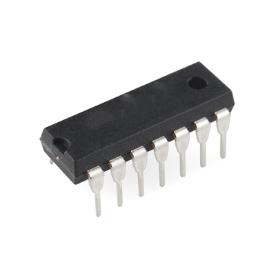
The 74155 is a dual BCD (Binary Coded Decimal) to 1-of-16 line decoder and driver. It is typically used in digital systems where a 4-bit BCD input is used to select one of 16 output lines. It is part of the 7400 series of integrated circuits and is commonly used for applications that require decoding binary inputs to activate specific output lines.
74155 IC Description:
The 74155 IC contains two independent BCD to 1-of-16 line decoders, each of which accepts a 4-bit BCD input (ranging from 0000 to 1001 in binary, which corresponds to decimal 0 to 9) and decodes it into one of 16 output lines. This type of IC is useful in applications such as driving 7-segment displays, memory address decoding, and multiplexing.
Key Features:
- Dual BCD to 1-of-16 Decoder/Driver: The IC contains two separate decoders that each convert a 4-bit BCD input into one of 16 outputs.
- Active-low Outputs: The IC’s outputs are active-low (i.e., the selected output will be LOW while all other outputs are HIGH).
- Binary Coded Decimal (BCD) Input: The IC accepts a 4-bit BCD input, which can represent decimal numbers 0 to 9.
- Output Drive Capability: The IC can drive TTL-compatible loads, which makes it suitable for driving displays, relays, or other components in digital circuits.
- Simple Control: The outputs are controlled by the BCD inputs, and the IC automatically selects the appropriate output based on the binary value of the BCD input.
Pin Configuration (16-pin package):
Here is the standard pinout for the 74155 IC:
- Pin 1 (A1): BCD input bit 1 for the first decoder.
- Pin 2 (B1): BCD input bit 2 for the first decoder.
- Pin 3 (C1): BCD input bit 3 for the first decoder.
- Pin 4 (D1): BCD input bit 4 for the first decoder.
- Pin 5 (Y1-0 to Y1-15): Output 0 to Output 15 for the first decoder (active-low).
- Pin 6 (Y1-1): Active-low output 1 for the first decoder.
- Pin 7 (Y1-2): Active-low output 2 for the first decoder.
- Pin 8 (Ground): Ground connection (GND).
- Pin 9 (Y2-0 to Y2-15): Output 0 to Output 15 for the second decoder.
- Pin 10 (Y2-1): Active-low output 1 for the second decoder.
- Pin 11 (Y2-2): Active-low output 2 for the second decoder.
- Pin 12 (Y2-3): Active-low output 3 for the second decoder.
- Pin 13 (D2): BCD input bit 4 for the second decoder.
- Pin 14 (C2): BCD input bit 3 for the second decoder.
- Pin 15 (B2): BCD input bit 2 for the second decoder.
- Pin 16 (A2): BCD input bit 1 for the second decoder.
How It Works:
The 74155 IC uses the 4-bit BCD inputs (A, B, C, and D) for each of the two decoders to select one of 16 output lines. These outputs are active-low, meaning that the selected output line will be driven LOW (active), while the others will be HIGH.
- BCD Input: The BCD input consists of 4 bits, which represent a decimal number from 0 to 9. For example:
- If the BCD input is 0000 (binary), the IC will activate output Y1-0 (or Y2-0 for the second decoder).
- If the BCD input is 0001 (binary), the IC will activate output Y1-1 (or Y2-1 for the second decoder), and so on.
- Active-low Outputs: Each of the 16 outputs is active-low, meaning only one of the output lines will be LOW (active) at a time, corresponding to the value of the BCD input. All other outputs will remain HIGH.
- Two Decoders: The IC has two independent decoders. Each decoder has its own set of 4-bit BCD inputs, and it will decode the input to drive the corresponding output.
Truth Table (for a single decoder):
| BCD Input (A, B, C, D) | Output |
|---|---|
| 0000 | Y0 (active-low) |
| 0001 | Y1 (active-low) |
| 0010 | Y2 (active-low) |
| 0011 | Y3 (active-low) |
| 0100 | Y4 (active-low) |
| 0101 | Y5 (active-low) |
| 0110 | Y6 (active-low) |
| 0111 | Y7 (active-low) |
| 1000 | Y8 (active-low) |
| 1001 | Y9 (active-low) |
| 1010 to 1111 | Outputs Y10 to Y15 (not used for BCD input) |
Note: The decoder only decodes the BCD inputs 0000 to 1001 (decimal 0 to 9). For inputs 1010 (decimal 10) through 1111 (decimal 15), the outputs Y10 to Y15 are not valid for BCD and may be unused.
Applications:
- 7-Segment Display Drivers: The 74155 IC is commonly used to drive 7-segment displays in digital clocks, meters, or other display applications where a 4-bit BCD input must be converted into a signal that activates the appropriate segments of the display.
- Memory Address Decoding: It can be used for memory address decoding where a 4-bit address needs to select one of several memory locations or devices.
- Multiplexing: The IC can be used in multiplexing circuits where multiple outputs are needed, and only one output is activated at a time.
- LED Driver: The 74155 can drive LEDs or other indicators, where each of the 16 outputs can control a separate LED.
- Switching Applications: It can be used in digital switching applications where one of several output lines must be activated based on a BCD input.
Electrical Characteristics:
- Supply Voltage (Vcc): Typically 5V (with a range of 4.5V to 5.5V).
- Output Drive Capability: The 74155 IC can drive TTL-compatible loads.
- Power Consumption: As a CMOS device, it consumes very little power when operating.
Example Application:
In a digital clock application, the 74155 can be used to decode the BCD input from the hours and minutes counter into signals that drive the 7-segment displays for each digit. The BCD inputs could come from a counter IC like the 74160, and the 74155 would decode the value and activate the correct output to drive each segment of the display.
Only logged in customers who have purchased this product may leave a review.
- Image
- SKU
- Rating
- Price
- Stock
- Availability
- Add to cart
- Description
- Content
- Weight
- Dimensions
- Additional information


Reviews
There are no reviews yet.