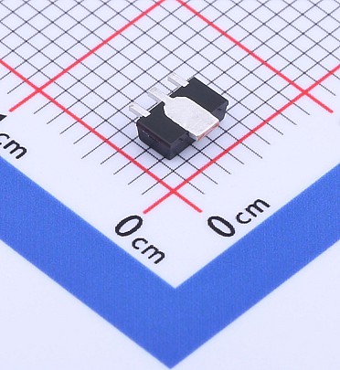
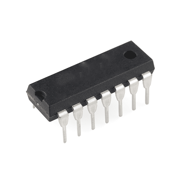
7491 (4-bit binary counter with an asynchronous reset)
SKU: 13856
Pick up from store
Shipping 2-3 business days
Description
The IC 7491 is a 4-bit binary counter with an asynchronous reset feature, commonly used in digital circuits for counting applications, such as frequency dividers or time-delay circuits. It’s part of the 7400 series of ICs and is widely used in various digital systems for counting or sequencing purposes.
7491 IC Description:
The 7491 is a 4-bit binary ripple counter that counts in binary from 0 to 15 (0000 to 1111 in binary). It can operate in asynchronous mode and provides a binary output corresponding to the current count. This IC is useful for applications requiring counting, timing, or frequency division.
Key Features:
- 4-bit Binary Counter: It can count from 0 to 15 (i.e., 4 bits).
- Asynchronous Reset: The counter can be asynchronously reset to zero by applying a logic LOW to the reset pin (pin 6), regardless of the clock state.
- Decade Counter Capability: When used with external components, it can be configured as a decade counter (counting from 0 to 9) for applications like clock dividers or decimal counters.
- Ripple Counter Configuration: The counter is implemented in a ripple configuration, meaning each bit (flip-flop) is clocked sequentially.
- Low Power Consumption: As part of the CMOS family, it consumes low power when not actively counting.
Pin Configuration (14-pin package):
Here’s the standard pinout for the 7491 4-bit binary counter:
- Q1: Output of the first flip-flop (least significant bit).
- Q2: Output of the second flip-flop.
- Q3: Output of the third flip-flop.
- Q4: Output of the fourth flip-flop (most significant bit).
- Clock (CLK): Input clock signal.
- Reset (CLR): Active-low reset input to clear the counter.
- Carry Out (CO): Output that generates a carry-out pulse when the counter reaches its maximum count (15).
- Vcc: Positive supply voltage (usually 5V).
- Ground (GND): Ground connection.
How it Works:
The 7491 IC is a binary counter that counts from 0 to 15 in binary. It operates as follows:
- Clock Input (CLK): Each rising edge of the clock signal increments the count by 1.
- Reset (CLR): When a LOW signal is applied to the reset input (pin 6), the counter resets to 0000 (binary 0), regardless of the clock state.
- Outputs (Q1, Q2, Q3, Q4): The binary count is represented on the four output pins, corresponding to the current value of the counter.
- Carry Out (CO): The carry-out pin generates a pulse (transition from LOW to HIGH) when the counter reaches the maximum value (1111 in binary, or 15). This can be used for cascading multiple counters or generating timing signals.
Applications:
- Frequency Division
- Digital Counters
- Pulse Generation
- Time Delay Circuits
- Decimal Counting
Electrical Characteristics:
- Supply Voltage (Vcc): Typically 5V (with a range of 3V to 15V depending on the IC specifications).
- Power Consumption: The IC consumes low power, typical of CMOS logic families.
- Operating Temperature Range: Usually, the IC operates within a temperature range of 0°C to 70°C.
Related Products
MAX485 TTL To RS485 Converter Module
74259 (8-bit addressable latch )
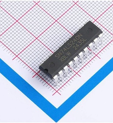
74240 (Octal 3-STATE Buffer/Line Driver/Line Receiver IC DIP-20 )
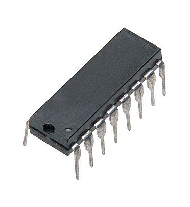
74160 (Synchronous 4-Bit Counter)
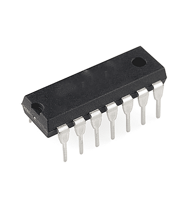
7437 (2-input NAND Gates)
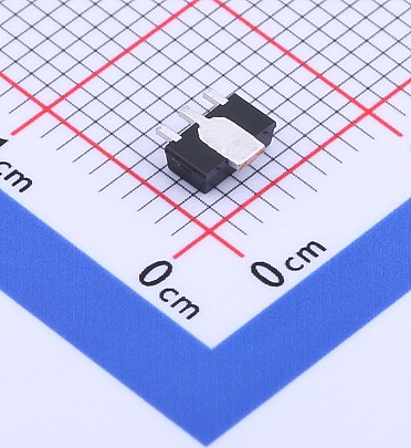
AMS1117 - ADJ - SOT-89 (ADJ Linear Voltage Regulator)
AMS1117 - 5 - SOT-89 (5V Linear Voltage Regulator)