74139 (Dual 2-Line to 4-Line Decoder/Demultiplexer)
SKU: 15365
Pick up from store
Shipping 2-3 business days
Description
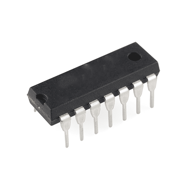
The 74139 is a Dual 2-Line to 4-Line Decoder/Demultiplexer. It is part of the 7400 series of ICs and is used in digital systems for applications requiring decoding or demultiplexing of binary signals. The IC provides two independent 2-to-4 line decoders, each with active-low outputs.
74139 IC Description:
The 74139 is a dual decoder/demultiplexer with 2-input binary code (2-line) decoded into 4 mutually exclusive output lines. The IC is designed to be used in applications such as address decoding, memory management, or data routing in digital systems. The 74139 is commonly used in systems that require efficient control and management of multiple lines based on a small number of input signals.
Key Features:
- Dual 2-to-4 Line Decoder: The 74139 contains two independent 2-to-4 line decoders, meaning each decoder takes two input lines and decodes them into four output lines.
- Active-Low Outputs: The outputs are active low, meaning the output is low (0) when selected and high (1) when not selected.
- Enable Inputs: Each of the two decoders has an enable input (G1 and G2). The decoder will only function when the enable inputs are active.
- Low Power Consumption: As a CMOS device, the 74139 has low power consumption while operating at high speeds.
- Synchronous Operation: The IC operates in a synchronous manner, meaning it decodes the input values in sync with the logic level of the inputs.
- High-Speed Operation: The IC operates at high speed, allowing it to be used in fast digital systems for decoding or routing.
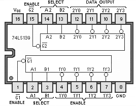
Pin Configuration (16-pin package):
Here is the pinout for the 74139:
- Pin 1 (G1): Enable input for Decoder 1.
- Pin 2 (A1): Input A for Decoder 1.
- Pin 3 (B1): Input B for Decoder 1.
- Pin 4 (Y1,0): Output 1 (active-low) for Decoder 1.
- Pin 5 (Y1,1): Output 2 (active-low) for Decoder 1.
- Pin 6 (Y1,2): Output 3 (active-low) for Decoder 1.
- Pin 7 (Y1,3): Output 4 (active-low) for Decoder 1.
- Pin 8 (Ground): Ground (0V).
- Pin 9 (Y2,0): Output 1 (active-low) for Decoder 2.
- Pin 10 (Y2,1): Output 2 (active-low) for Decoder 2.
- Pin 11 (Y2,2): Output 3 (active-low) for Decoder 2.
- Pin 12 (Y2,3): Output 4 (active-low) for Decoder 2.
- Pin 13 (B2): Input B for Decoder 2.
- Pin 14 (A2): Input A for Decoder 2.
- Pin 15 (G2): Enable input for Decoder 2.
- Pin 16 (Vcc): Supply voltage (typically 5V).
Related Products

OLFA Plastic Cutter Knife for Hook Blades (Acrylic Cutting)
MAX485 TTL To RS485 Converter Module
74259 (8-bit addressable latch )
74240 (Octal 3-STATE Buffer/Line Driver/Line Receiver IC DIP-20 )
74160 (Synchronous 4-Bit Counter)
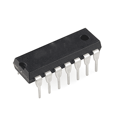
7437 (2-input NAND Gates)
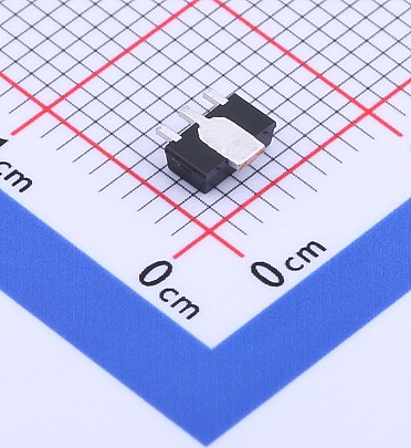
AMS1117 - ADJ - SOT-89 (ADJ Linear Voltage Regulator)